The Infrastructure Monitoring System Achievements
The Infrastructure Monitoring System (IMS) has the objective to identify risks and threats surrounding the first responders based on the visual detection of damages on structures and infrastructures in the critical event area, using advanced Machine Learning algorithms for anomalies detection.
The automated screening algorithm for damage recognition, implemented in IMS, is a Deep Convolutional Neural Networks (DCNN) trained for item detection and localisation. Deep Neural Networks need a significant number of examples of each object class to be detected (in the order of several thousands) to be sufficiently robust. However, when the target object classes are attributable to anomalies of some kind, which, in the case of structural/infrastructural damages, may be rare, datasets of limited volume are available. Because of this reason, WP4 activities foresee the creation of a tailor-made dataset of semi-synthetic images to be used in conjunction with the dataset of real-world dataset of annotated damages available (like the one belonging to EUCENTRE). The semi-synthetic generation procedure produces images with adequately comparable characteristics to real ones, in support to the operations of training and validation of object detection algorithms.
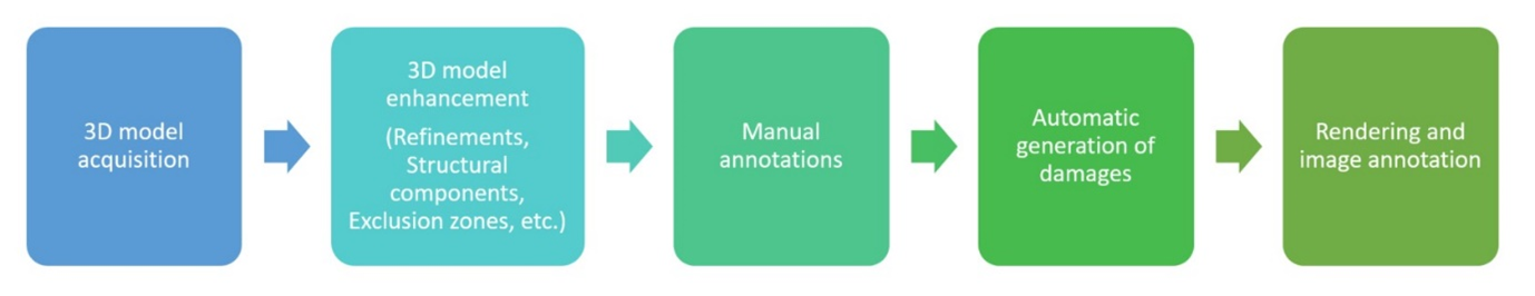
Differently from other artificial datasets, the semi-synthetic images are created starting from 3D models of real buildings and infrastructures, as opposed to the visual rendering of CAD-based models. Starting from aerial imagery from UAV surveys, the application of the Structure for Motion (SfM) photogrammetric method allows obtaining 3D point cloud or surface models, with colours and textures as close to photographic quality as possible, provided that images have a suitable resolution for a realistic digital reconstruction. Then, the 3D models are further elaborated, and enhanced through the application of artificially generated common structural damages, according to the workflow in the following Figure 1.
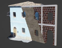
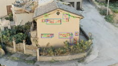
To provide a first generalization of the dataset, some of the most common typologies of structures and technologies were selected based on their use and diffusion in urban environments, limited at present to European seismic prone countries. Depending on the architectural and structural configurations of the selected structural types, the construction details are artificially implemented in available 3D models according to typical rules of art, design codes prescriptions and examples from technical textbooks (Figure 2).
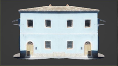
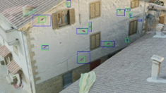
The definition of the damage patterns, location and visual appearance for each of the considered structural types is based on the analysis of data retrieved from reconnaissance surveys after recent earthquakes and from experimental campaigns performed to evaluate the seismic vulnerability of both reinforced concrete and unreinforced masonry structures. After the enhancement of the model, the position in which the damages will be generated has to be specified, the “Areas of Damage” (Figure 3), namely the parts of the model in which the damages will occur.
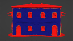
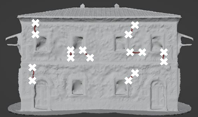
Since the goal of the methodology is to obtain a realistic simulation from not only a visual but also from a structural point of view, a manual annotation input of the models is needed from experts in the field. However, the set of annotations, from which the program can infer the remaining damage positions, is reduced to a minimum (mainly the positioning of the cracks as shown in Figure 4). More in general, all the damages have a high degree of parametrization, by specifying and/or randomizing their thickness, length, size, depth.
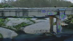
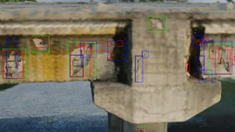
The last phase of the process is focused on the creation of realistic images, with bounding box annotation. During this step, the user selects the background, the position and intensity of the lights, the initial camera angle and position, as well as the path(s) that the camera will follow during the rendering, to emulate the flight path(s) of an inspection drone. Given this setup, the program can now render all the images requested. After rendering, a python script is used to add, at each image, a bounding box around each damage and to create a corresponding xml file in Pascal VOC format, a commonly adopted annotation format for object detection.
The dataset of semi-synthetic images created according to this procedure will then be used for training and testing of the damage detection algorithms implemented in IMS.