Acoustic Detection System Hardware by Microlfown AVISA
The main objective of the Acoustic Detection System (ADS) is to detect and locate emergency events near the first responders using received acoustic measurements. ADS will detect and locate acoustic events including explosions, gunshots, human voices (e.g., screams, asking for help) and whistling in the operations. In addition, ADS should be able to recognise and locate overlapping sound events such as a woman screaming, while an explosion is taking place there. In the final version, these results will be fused with the ones coming from a visual modality (if it’s available), in order to improve the overall system’s performance.
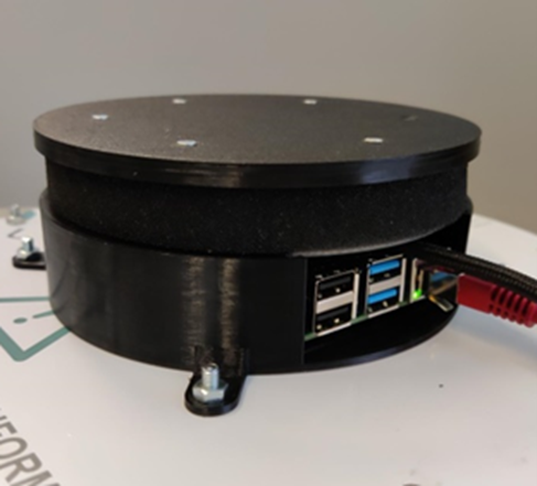
Regarding the hardware, a new Acoustic Vector Sensor (AVS) array has been developed by Microflown AVISA (www.microflown-avisa.com) under WP6. The hardware prototype was manufactured and tested in Microflown AVISA premises. The AVS array and required signal conditioning board is added to the processor required for running the algorithms for detection and localisation of the sound events. All these PCBs packed in a proper housing that can be mounted on different platform including a UAV.
The velocity flowns (acoustic sensors with capability of measuring particle velocity) included in the AVS array provide a complete directional sensitivity around the array to be able to receive and locate acoustic signal from different directions.
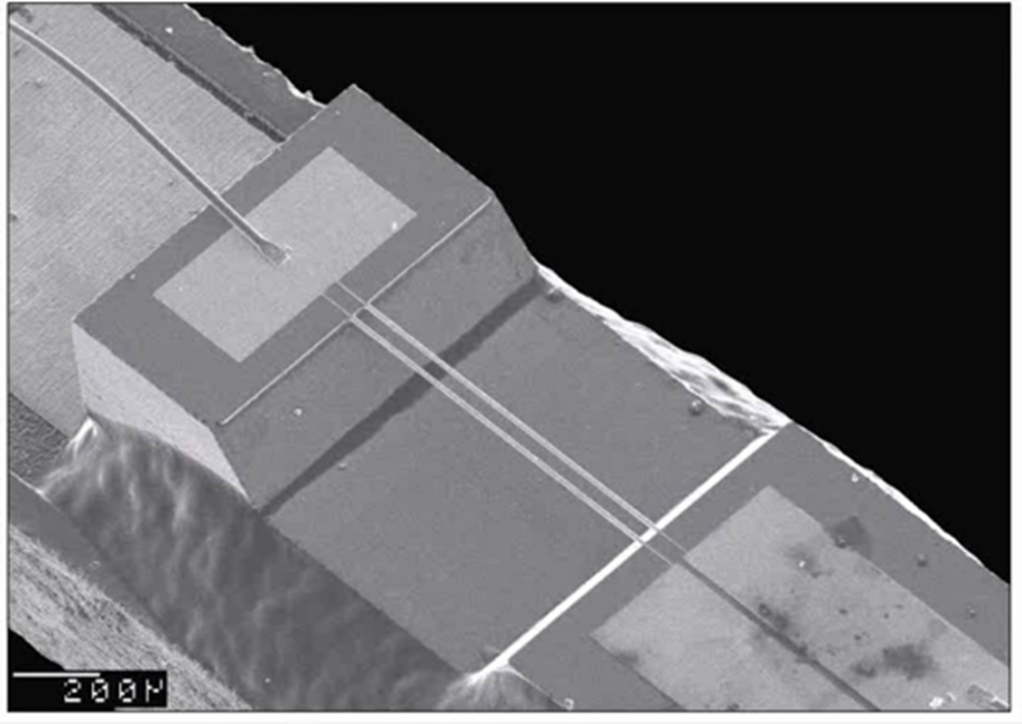
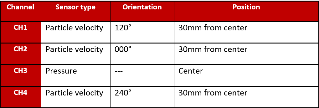
This is facilitated by the fact that velocity flowns are directional sensors and placed in a 120° orientation from each other. The place and orientation of the velocity flowns and pressure sensor on the AVS array are shown in Table 1. The pressure sensor which is omnidirectional placed in the centre of the array. The orientation of 000° points toward the connector side of the device.
Validation of the ADS Hardware
ADS hardware validation tasks are performed to validate the capabilities of the ADS hardware for sensing the acoustic events. Validation of ADS is planned and performed in three steps.
- Four channel/sensor Recording.
- Angular Sensitivity.
- Outdoor tests.
Four Channel recording are performed in hardware laboratory in AVISA for recording the acoustic environment noise. ADS hardware is powered up with a USB power supply and was connected to a network with Ethernet cable. ADS hardware records acoustic ambient/environment noise and different sound sources including human speech in the hardware laboratory. There are four sensors in the array and each sensor equals to a channel, that’s why this test is called ‘’Four Channel Recording’’.
Angular sensitivity of each sensor in AVS array of the ADS hardware is measured in the anechoic chamber in AVISA premises using a turning table for fixing the ADS hardware on it and a fixed speaker for playing a sound file (as a sound source) as shown in Figure 3. The white noise is used as a sound source in this experiment because it has a wide frequency spectrum.

ADS hardware for the angular sensitivity test is setup for recording as described. The array is turned in the steps of 20 degree and the received signal at the AVS array (4 channels) is recorded for 6 seconds at each step. These recordings are analysed for angular reception of the array.
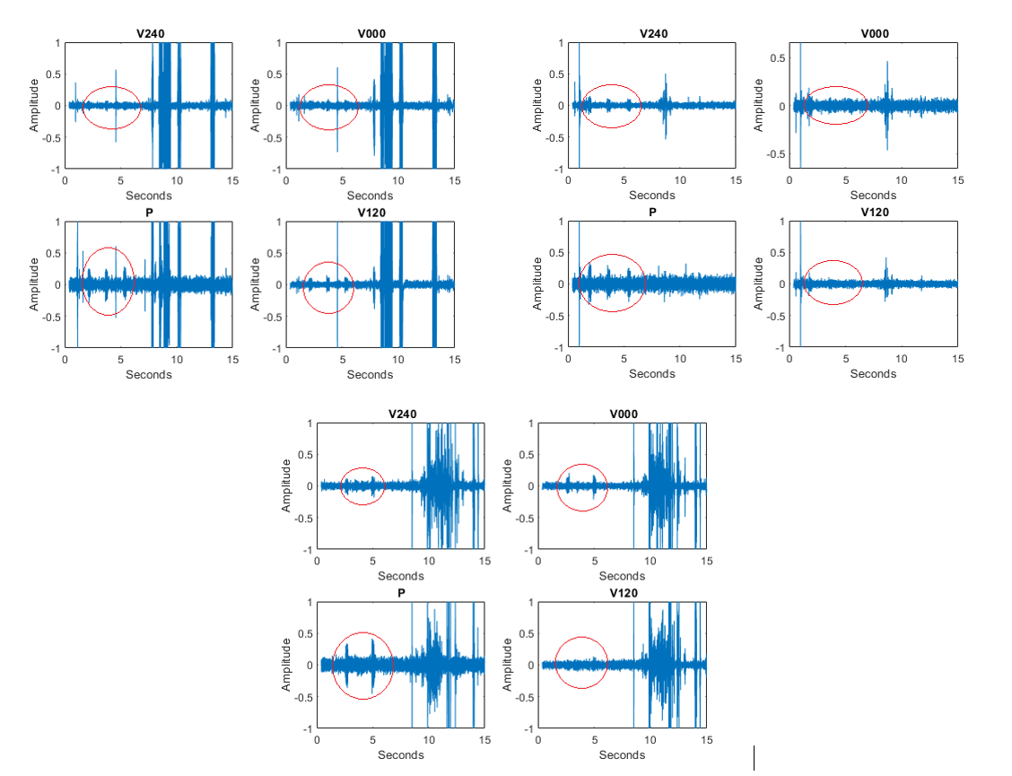
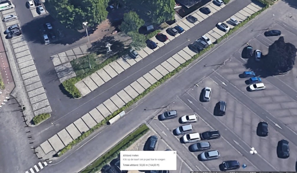
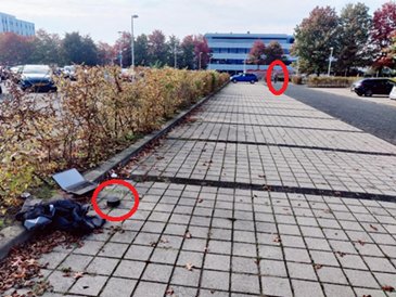
ADS array has a wide frequency range and can receive different sound sources including human voices. For validation of the capability of the ADS array in receiving human voice at outdoor in a distance of 50 m, a set of outdoor tests is performed in an uncontrolled environment (a parking lot near AVISA). In this set of tests considering the objectives of the WP6, ADS hardware is located 50 meters away from a person. The person repeats the word “test” three times and the signal received at the array (four sensors) are recorded for further analysis. After the first recording, the array is rotated manually and the tests are repeated for the new angle in which the array is positioned. The array in this set of tests is positioned at three different angles (0, 120, 240 degrees) respect to the line from the centre of the array to the person standing 50 m away from the array.
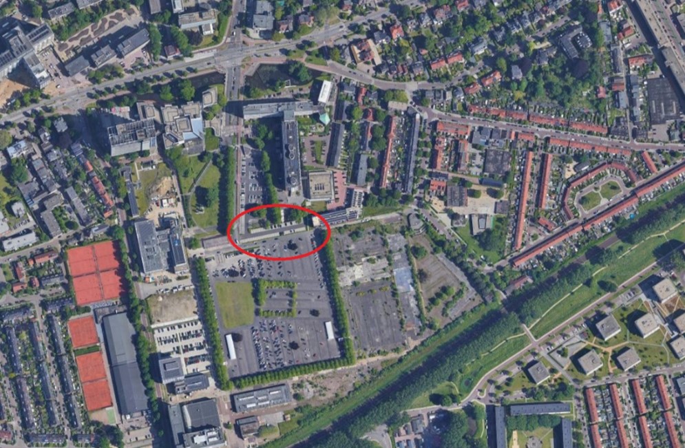
The outdoor tests are performed in the parking lot in Arnhem outside the AVISA building as shown in Figure 4 and Figure 5. The parking lot shown in Figure 6 is in an area with medium traffic, buildings and human population around. The position of the array and person standing far away from the array related to the outdoor test are shown in Figure 6.
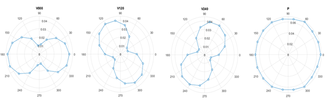
The results of the analysis performed on the recordings obtained from the anechoic chamber tests are presented in the form of an angular reception plot for each channel as shown in Figure 7.
Human speech was recorded from 50-meter distance and for three different orientation of the array in the outdoor tests explained above. The received audio signal were analysed and plotted in MATLAB. The received signals are shown in Figure 8 for all four channels and three different orientation of the array. The signals are audio files and the area shown in the red ovals are related to the voice of the person repeating the word ‘’test” from a 50 m distance. By listening to the files, we could also hear the sound of person in 50 m distance. These tests proved the capability of the array in receiving human speech from 50 m distance outdoor as the object of this test.